
 資料結構
資料結構 網路
網路 關係型資料庫管理系統
 作業系統
作業系統 Java
Java iOS
iOS HTML
HTML CSS
CSS Android
 Python
 C語言程式設計
 C++
C++ C#
C# MongoDB
 MySQL
MySQL Javascript
 PHP
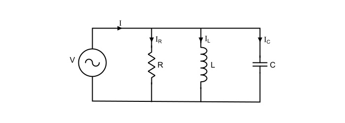
PHP並聯RLC電路:分析和示例問題
考慮圖中所示的並聯RLC電路,其中電阻R、電感L和電容C並聯連線,I(RMS)為總電源電流。在並聯電路中,三個元件上的電壓V(RMS)保持相同。因此,為方便起見,電壓可以作為參考相量。
這裡,
$$\mathrm{\mathit{V}=\mathit{IZ}=\frac{\mathit{I}}{\mathit{Y}}}$$
其中,
- Z= 並聯電路的總阻抗,
- Y=1/Z= 並聯電路的導納。
並聯電路的導納由下式給出:
$$\mathrm{\mathit{Y}=\frac{1}{\mathit{R}}+\frac{1}{\mathit{j\omega L}}+\mathit{j\omega C}=\frac{1}{\mathit{R}}+ {\mathit{j}}(\mathit{\omega C}-\frac{1}{\mathit{\omega L}})=\mathit{G}+\mathit{jB}}$$
其中,
- G=1/R= 電路的電導,
- B=1/X= 電路的電納,
$$\mathrm{導納幅值,|\mathit{Y}|=\sqrt{(\frac{1}{\mathit{R}})^{2}+(\mathit{\omega C}-\frac{1}{\mathit{\omega L}})^{2}}}$$
$$\mathrm{導納相角,\:\varphi=\tan^{-1}(\frac{\mathit{\omega C}-\frac{1}{\mathit{\omega L}}}{\frac{1}{\mathit{R}}})=\tan^{-1}(\mathit{R}(\mathit{\omega C}-\frac{1}{\mathit{\omega L}}))}$$
因此,
$$\mathrm{\mathit{I}=\mathit{VY}=\mathit{V}×\sqrt{(\frac{1}{\mathit{R}})^{2}+(\mathit{\omega C}-\frac{1}{\mathit{\omega L}})^{2}}\angle\tan^{-1}(\mathit{R}(\mathit{\omega C}-\frac{1}{\mathit{\omega L}}))}$$
因此,
$$\mathrm{電源電流幅值,| \mathit{I}|=\mathit{V}×\sqrt{(\frac{1}{\mathit{R}})^{2}+(\mathit{\omega C}-\frac{1}{\mathit{\omega L}})^{2}}}$$
$$\mathrm{導納相角,\:\varphi=\tan^{-1}(\mathit{R}(\mathit{\omega C}-\frac{1}{\mathit{\omega L}}))}$$
因此,支路電流為
$$\mathrm{電阻電流,\mathit{I}_{\mathit{R}}=\frac{\mathit{V}}{\mathit{R}}=\frac{|\mathit{V}|\angle0^{\circ}}{\mathit{R}}=|\mathit{I}_{\mathit{R}}|\angle0^{\circ}}$$
$$\mathrm{電感電流,\mathit{I}_{L}=\frac{\mathit{V}}{\mathit{X}_{L}}=\frac{|\mathit{V}|\angle0^{\circ}}{\mathit{j\omega L}}=\frac{|\mathit{V}|}{\mathit{\omega L}}\angle(0^{\circ}-90^{\circ})=|\mathit{I}_{L}|\angle(-90^{\circ})}$$
$$\mathrm{電容電流,\mathit{I}_{c}==\frac{\mathit{V}}{\mathit{X}_{c}}=|\mathit{V}|\angle0^{\circ}(\mathit{j\omega C})=|\mathit{V}| \mathit{\omega C}\angle(+90^{\circ})=|\mathit{I}_{L}|\angle(+90^{\circ})}$$
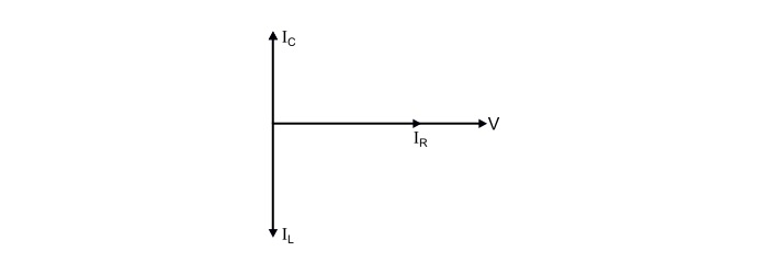
因此,很明顯
電阻電流IR與電源電壓同相。
電感電流IL滯後於外加電壓90°。
電容電流IC超前於外加電壓90°。
並聯RLC電路中的總電源電流是上述三個電流的相量和(粗體字母),而不是算術和,即
$$\mathrm{\mathit{I}=\mathit{I}_{\mathit{R}}+\mathit{I}_{\mathit{L}}+\mathit{I}_{\mathit{C}}}$$
$$\mathrm{電源幅值,|\mathit{I}|=\sqrt{(\mathit{I}_{\mathit{R}})^2+(\mathit{I}_{\mathit{C}}-\mathit{I}_{\mathit{L}})^2}}$$
電源電流I的相角取決於IC和IL的大小。
並聯RLC電路的三種情況
情況1 – 當,|IL|>|Ic| 或 XL<XC

這裡,
電源電流滯後於電源電壓φ°。
電路的功率因數滯後。
並聯RLC電路表現為感性電路。
情況2 – 當,|IL|<|Ic| 或 XL>𝐶XC

這裡,
電源電流超前於電源電壓φ°。
電路的功率因數超前。
並聯RLC電路表現為容性電路。
情況3 – 當,|IL| = |Ic| 或 XL = XC

這裡,
電源電流與電源電壓同相,即角度φ = 0°。
電源電流等於電阻電流,即I = IR。
電路的功率因數為1。
並聯RLC電路表現為純電阻電路。
在這種情況下,並聯RLC電路稱為並聯諧振電路。
並聯諧振
當導納的虛部為零時,並聯RLC電路中發生諧振現象。然而,導納為
$$\mathrm{\mathit{Y}=\mathit{G}+\mathit{jB}=\frac{1}{\mathit{R}}+\mathit{j}(\mathit{\omega C}-\frac{1}{\mathit{\omega L}})}$$
在諧振時,
$$\mathrm{\mathit{\omega C}-\frac{1}{\mathit{\omega L}}=0}$$
因此,
$$\mathrm{\mathit{Y}=\frac{1}{\mathit{R}}}$$
發生諧振的頻率為
$$\mathrm{\mathit{\omega_{0} C}-\frac{1}{\mathit{\omega_{0} L}}=0}$$
$$\mathrm{\Rightarrow\:\mathit{\omega_{0}}=\frac{1}{\sqrt{\mathit{LC}}}}$$
諧振時的電源電流(I)為
$$\mathrm{\mathit{I}=\mathit{VY}=\frac{\mathit{V}}{\mathit{R}}=\mathit{I}_{\mathit{R}}}$$
$$\mathrm{\Rightarrow\:\mathit{V}=\mathit{IR}=\mathit{I}_{\mathit{R}}\mathit{R}}$$
電感電流幅值(IL)為
$$\mathrm{|\mathit{I}_{L}|=\frac{\mathit{V}}{\mathit{\omega L}}=\frac{\mathit{IR}}{\mathit{\omega L}}=\mathit{IQ}_{0}}$$
$$\mathrm{其中,\mathit{Q}_{0}=\frac{\mathit{R}}{\mathit{\omega L}}=品質因數}$$
諧振時電容電流幅值(IC)為
$$\mathrm{|\mathit{I}_{c}|=\mathit{V}(\mathit{\omega C})=\mathit{I}(\mathit{\omega R C})=\mathit{IQ}_{0}}$$
並聯諧振結論 -
XL=XC 或 IL = IC,因此諧振頻率,ω0=$1/\sqrt{LC}$。
Y=1/R,即導納值最小。
Z=R,即阻抗最大。
IR=V/R= 電源電流(I)
| IL |=| IC |=IQ0
並聯諧振電路的功率因數為1。
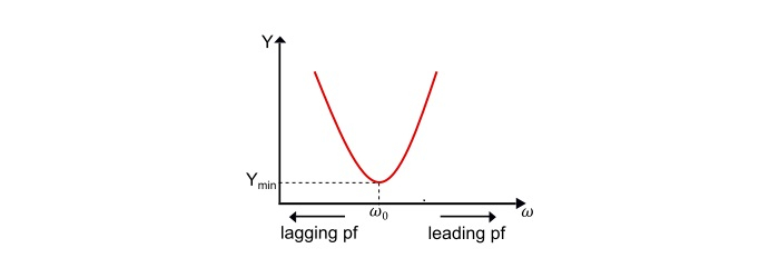
導納-頻率曲線
$$\mathrm{\mathit{Y}=\frac{1}{\mathit{R}}+\mathit{j}(\mathit{\omega C}-\frac{1}{\mathit{\omega L}})}$$
這裡,
在低於諧振頻率的頻率下,XL < XC 或 IL > IC ,因此電路表現為感性電路,功率因數滯後。
在高於諧振頻率的頻率下,XL > XC 或 IL < IC ,因此電路表現為容性電路,功率因數超前。
在諧振頻率下,XL = XC 或 IL = IC ,因此電路表現為純電阻電路,功率因數為1。
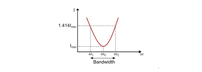
電流-頻率曲線
$$\mathrm{\mathit{I}=\mathit{VY}\:或\:\mathit{I}\:\alpha\:\mathit{Y}}$$
因此,並聯RLC電路的電流與頻率曲線與導納與頻率曲線相同。
參考電流-頻率曲線,
$$\mathrm{下截止頻率,\mathit{\omega}_{1}=-\frac{1}{2\mathit{RC}}+\sqrt{(\frac{1}{2\mathit{RC}})^2+\frac{1}{\mathit{LC}}}}$$
$$\mathrm{上截止頻率,\omega_{2}=+\frac{1}{2\mathit{RC}}+\sqrt{(\frac{1}{2\mathit{RC}})^2+\frac{1}{\mathit{LC}}}}$$
電路的頻寬為
$$\mathrm{BW=\mathit{\omega}_{2}-\mathit{\omega}_{1}=\frac{1}{\mathit{RC}}=\frac{\mathit{\omega}_{0}}{\mathit{\omega}_{0}\mathit{RC}}=\frac{\mathit{\omega}_{0}}{Q_{0}}}$$
另外,
$$\mathrm{\mathit{\omega}_{1}\:\mathit{\omega}_{2}=\frac{1}{\mathit{LC}}=\mathit{\omega}_{0}^2}$$
$$\mathrm{\Rightarrow\:\mathit{\omega}_{0}=\sqrt{(\mathit{\omega}_{1}\:\mathit{\omega}_{2})}}$$
因此,諧振頻率是半功率頻率的幾何平均值。
並聯RLC電路的品質因數
$$\mathrm{∵\mathit{Q}\:−因數=\frac{無功功率}{有功功率}=\frac{\mathit{R}}{\mathit{\omega L}}=\mathit{\omega RC}}$$
在諧振時,
$$\mathrm{\mathit{Q}_{0}-因數=\frac{\mathit{R}}{\omega_{0}\mathit{L}}=\omega_{0}\mathit{RC}}$$
由於諧振頻率為
$$\mathrm{\omega_{0}=\frac{1}{\sqrt{\mathit{LC}}}}$$
因此,並聯諧振電路的品質因數為
$$\mathrm{\mathit{Q}_{0}-因數=\frac{\mathit{R}}{\omega_{0}\mathit{L}}=\mathit{R}\frac{\sqrt{\mathit{LC}}}{\mathit{L}}=\mathit{R}\sqrt{\frac{\mathit{C}}{\mathit{L}}}}$$
數值示例
並聯RLC電路中的外加電壓由下式給出:
$$\mathrm{
u=100sin(314t+\frac{\pi}{4})V}$$
如果R、L和C的值分別為30 Ω、1.3 mH和30 μF,求電源提供的總電流。另外,求諧振頻率(Hz)和相應的品質因數。
解決方案
外加電壓的RMS值為
$$\mathrm{\mathit{V}=\frac{100\angle45^{\circ}}{\sqrt{2}}=70.72\angle45° V}$$
$$\mathrm{角頻率,\omega=314 rad/sec}$$
這裡,
$$\mathrm{導納,\mathit{Y}=\frac{1}{\mathit{R}}+j(\omega \mathit{C}-\frac{1}{\omega \mathit{L}})}$$
$$\mathrm{∵(\omega C-\frac{1}{\omega L})=((314×30×10^{−6})-(\frac{1}{314×1.3×10^{−3}}))=-2.439S}$$
$$\mathrm{∴\mathit{Y}=\frac{1}{30}+j(-2.439)=(0.033−j2.439)}$$
$$\mathrm{|\mathit{Y}|=\sqrt{(0.033)^2+(-2.439)^2}=2.439 S}$$
$$\mathrm{\varphi=\tan^{-1}(-\frac{2.439}{0.033})=-89.22^{\circ}}$$
因此,電源提供的電流為
$$\mathrm{\mathit{I}=\mathit{VY}=70.72\angle45°×2.439\angle-89.22°=172.486\angle-44.22°A}$$
諧振頻率由下式給出:
$$\mathrm{\mathit{f}_{0}=\frac{1}{2\pi\sqrt(\mathit{LC})}=\frac{1}{2\pi\sqrt{1.3×10^{−3}×30×10^{−6}}}=806.32 Hz}$$
對應於諧振頻率的品質因數為
$$\mathrm{\mathit{Q}_{0}-因數=\mathit{R}\sqrt{\frac{\mathit{C}}{\mathit{L}}}=30×\sqrt{\frac{30×10^{−6}}{1.3×10^{−3}}}=4.557}$$

18K+ 次檢視
