- Arduino 教程
- Arduino - 首頁
- Arduino - 概述
- Arduino - 開發板描述
- Arduino - 安裝
- Arduino - 程式結構
- Arduino - 資料型別
- Arduino - 變數與常量
- Arduino - 運算子
- Arduino - 控制語句
- Arduino - 迴圈
- Arduino - 函式
- Arduino - 字串
- Arduino - 字串物件
- Arduino - 時間
- Arduino - 陣列
- Arduino 函式庫
- Arduino - I/O 函式
- Arduino - 高階I/O函式
- Arduino - 字元函式
- Arduino - 數學庫
- Arduino - 三角函式
- Arduino 高階應用
- Arduino - Due & Zero
- Arduino - 脈寬調製 (PWM)
- Arduino - 隨機數
- Arduino - 中斷
- Arduino - 通訊
- Arduino - I2C (積體電路)
- Arduino - SPI (序列外設介面)
- Arduino 專案
- Arduino - 閃爍LED
- Arduino - 漸變LED
- Arduino - 讀取模擬電壓
- Arduino - LED條形圖
- Arduino - 鍵盤登出
- Arduino - 鍵盤訊息
- Arduino - 滑鼠按鍵控制
- Arduino - 鍵盤序列埠
- Arduino 感測器
- Arduino - 溼度感測器
- Arduino - 溫度感測器
- Arduino - 水位檢測/感測器
- Arduino - PIR感測器
- Arduino - 超聲波感測器
- Arduino - 連線開關
- 電機控制
- Arduino - 直流電機
- Arduino - 伺服電機
- Arduino - 步進電機
- Arduino 與聲音
- Arduino - 音調庫
- Arduino - 無線通訊
- Arduino - 網路通訊
- Arduino 有用資源
- Arduino - 快速指南
- Arduino - 有用資源
- Arduino - 討論
Arduino - LED條形圖
此示例演示如何讀取模擬引腳 0 上的模擬輸入,將 `analogRead()` 的值轉換為電壓,並將其列印到 Arduino 軟體 (IDE) 的序列埠監視器。
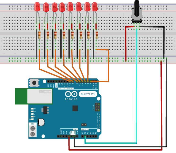
所需元件
您將需要以下元件:
- 1 個 麵包板
- 1 個 Arduino Uno R3
- 1 個 5kΩ 可變電阻器(電位器)
- 2 個 跳線
- 8 個 LED 或您可以使用(如下所示的 LED 條形圖顯示)
步驟
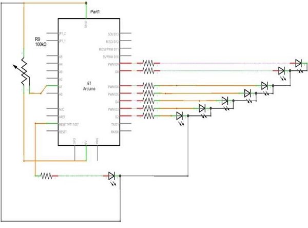
按照電路圖,將元件連線到麵包板,如下圖所示。
程式
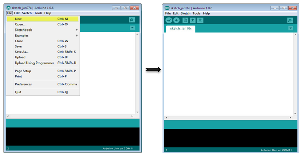
在您的計算機上開啟 Arduino IDE 軟體。使用 Arduino 語言進行編碼將控制您的電路。點選“新建”開啟一個新的程式檔案。
10 段 LED 條形圖
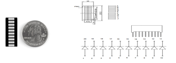
這些 10 段條形圖 LED 具有多種用途。它們具有緊湊的尺寸和簡單的連線方式,易於用於原型設計或成品。本質上,它們是 10 個獨立的藍色 LED 整合在一起,每個 LED 都有獨立的陽極和陰極連線。
它們也有黃色、紅色和綠色。
注意 - 這些條形圖的引腳排列可能與資料表上的說明有所不同。將器件旋轉 180 度可以糾正此差異,使引腳 11 成為第一個引腳。
Arduino 程式碼
/*
   LED bar graph
   Turns on a series of LEDs based on the value of an analog sensor.
   This is a simple way to make a bar graph display.
   Though this graph uses 8LEDs, you can use any number by
      changing the LED count and the pins in the array.
   This method can be used to control any series of digital
      outputs that depends on an analog input.
*/

// these constants won't change:
const int analogPin = A0; // the pin that the potentiometer is attached to
const int ledCount = 8; // the number of LEDs in the bar graph
int ledPins[] = {2, 3, 4, 5, 6, 7, 8, 9}; // an array of pin numbers to which LEDs are attached

void setup() {
   // loop over the pin array and set them all to output:
   for (int thisLed = 0; thisLed < ledCount; thisLed++) {
      pinMode(ledPins[thisLed], OUTPUT);
   }
}

void loop() {
   // read the potentiometer:
   int sensorReading = analogRead(analogPin);
   // map the result to a range from 0 to the number of LEDs:
   int ledLevel = map(sensorReading, 0, 1023, 0, ledCount);
   // loop over the LED array:
   for (int thisLed = 0; thisLed < ledCount; thisLed++) {
      // if the array element's index is less than ledLevel,
      // turn the pin for this element on:
      if (thisLed < ledLevel) {
         digitalWrite(ledPins[thisLed], HIGH);
      }else { // turn off all pins higher than the ledLevel:
         digitalWrite(ledPins[thisLed], LOW);
      }
   }
}
程式碼說明
程式的工作原理如下:首先,讀取輸入。將輸入值對映到輸出範圍,在本例中為十個 LED。然後設定一個for 迴圈來迭代輸出。如果系列中的輸出編號小於對映的輸入範圍,則將其開啟。否則,將其關閉。
結果
當模擬讀取值增加時,您將看到 LED 一個接一個地亮起;當讀取值減少時,LED 一個接一個地熄滅。
廣告